BACK
E-manage Plug & Play Harness
Written by: Daox
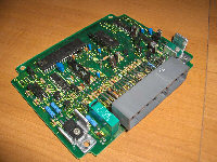
One of the main components in the 3E-ZE project is my nice new and shiny Greddy E-manage Ultimate. Of course I never really liked the idea of cutting into existing wiring on my car. A while back I had read about someone making a harness so they didn't have to cut into existing wiring. So, I did a little digging on Tercel Online's forums and found that Ugabuga did in fact make one of these for his car. I inquired some and set about gathering parts. To make a harness such as this you will need the following:
- Spare ECU from a car with the same engine as yours or one with similar connectors
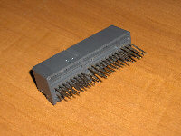
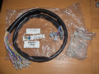
- The connector and some wire of the harness that connects to the ECU
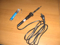
- Screw driver
- Soldering iron and solder
- Wire
- Wire cutter and stripper
- ECU pinout diagram
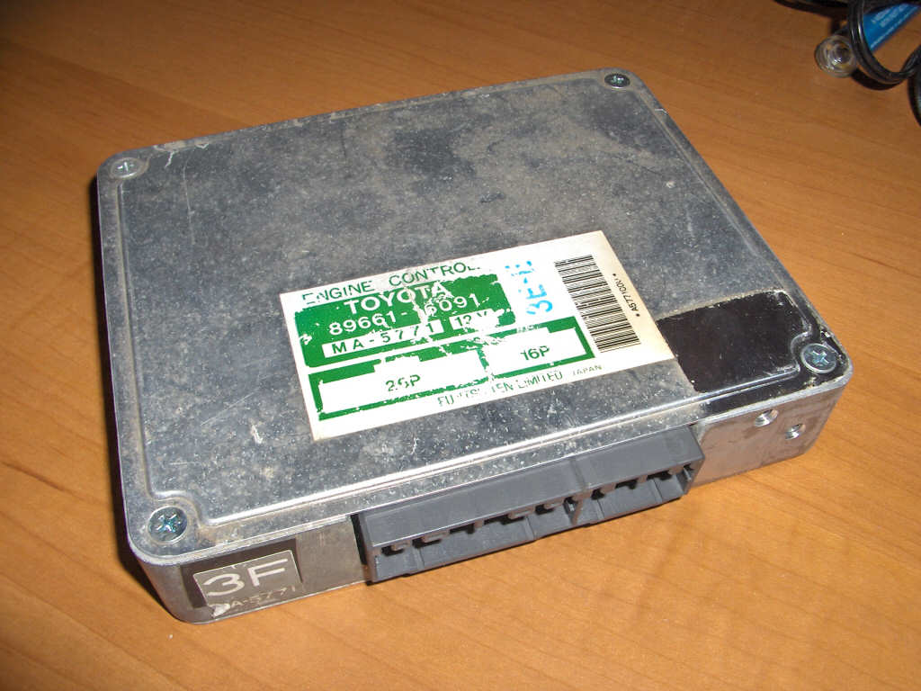
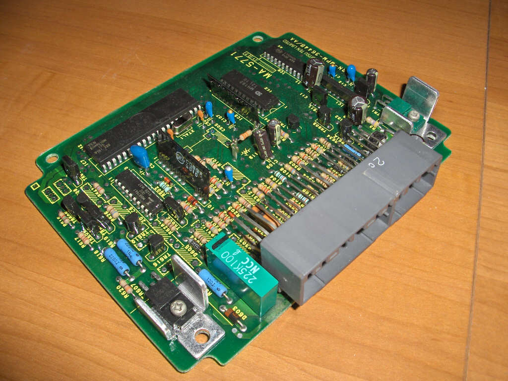
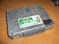
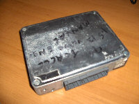
Ok, so lets get started. First we have to get the ECU, and crack it open. Its very easy. Just unscrew the four screws (per side) holding the two plates on the casing. Note, the connector had already been clipped off when I took these pictures.
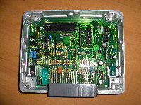
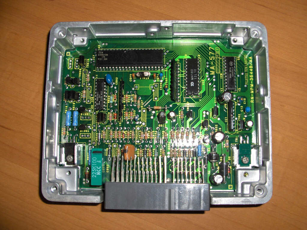
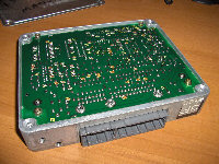
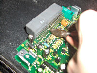
Once both of the plates are removed you can remove the four screws holding the ECU's board to the casing. Once those are out you should be able to pull the board completely out of the casing. Again, note the connector had already been clipped off when I took these pictures.
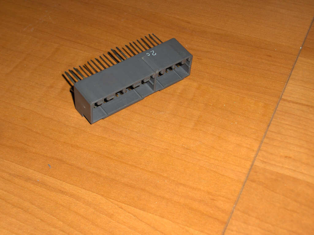
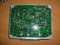
Now we get to get that connector off of there. Take a wire cutter and start cutting the leads at their base closest to the pc board. Sorry about the horrible picture quality, but I think you get the picture.
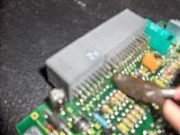
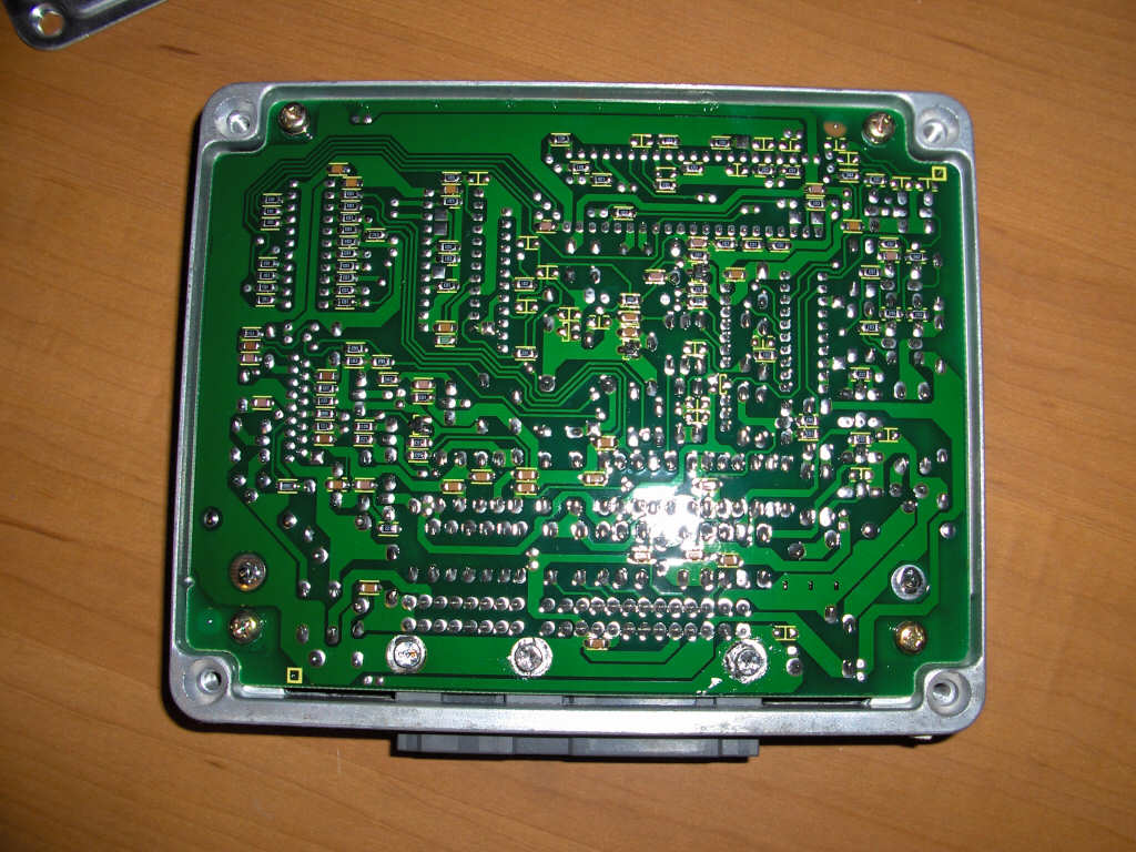
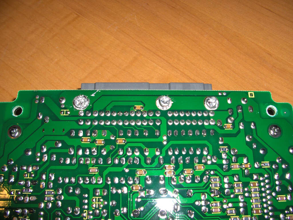
Now most would think that that would be enough to get the connector off. Well those tricky engineers at Toyota had different plans. If you look at the underside of the board you will see three screws, and most likely the heads of the screws will be filled with solder. I suppose there are a few ways to handle this. The first and probably best way would be to get your soldering iron and solder sucker out. Heat up the solder and suck it out of the head so you can remove the screws. I, however, didn't have a solder sucker on hand. So, I simply heated up the screws until they melted out of the connector. It took a while for the heat to transfer but it worked out pretty good. Just pull while heating and it'll pop out.
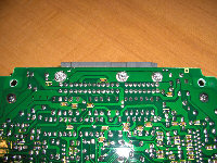

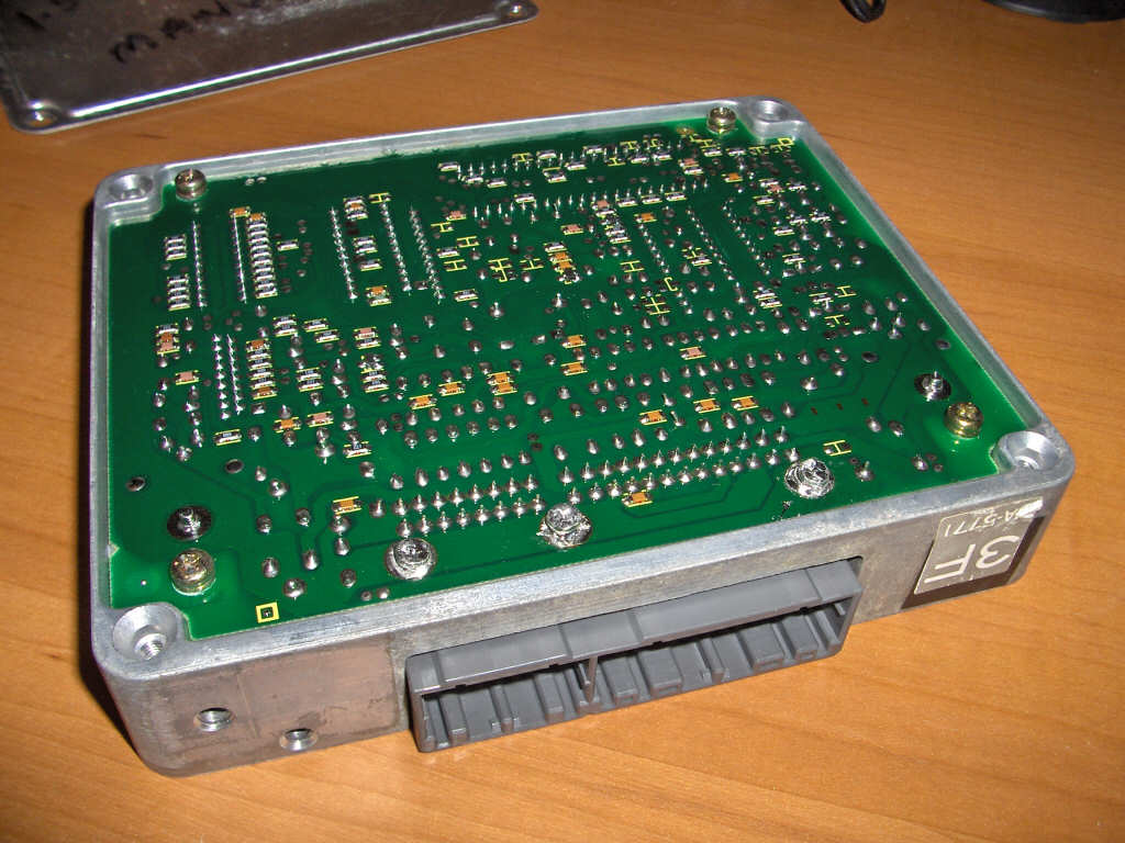
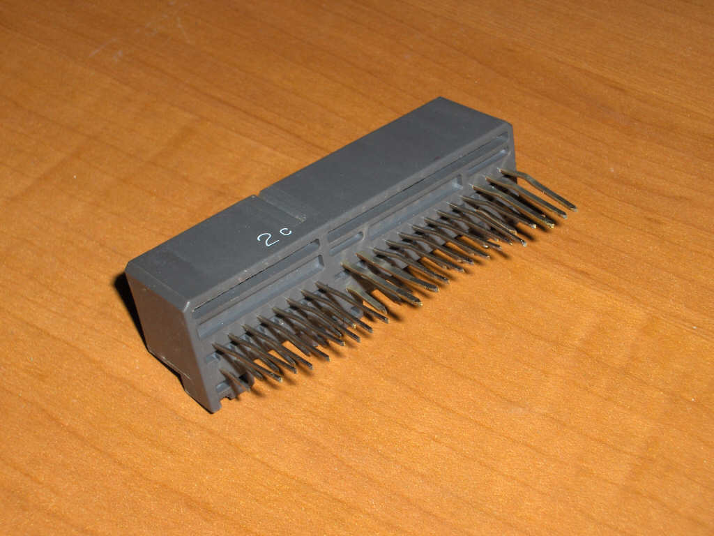
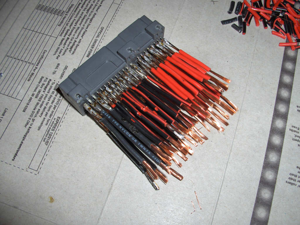
After you get the connector off you should straighten the leads out on it so you can easily solder to them later.
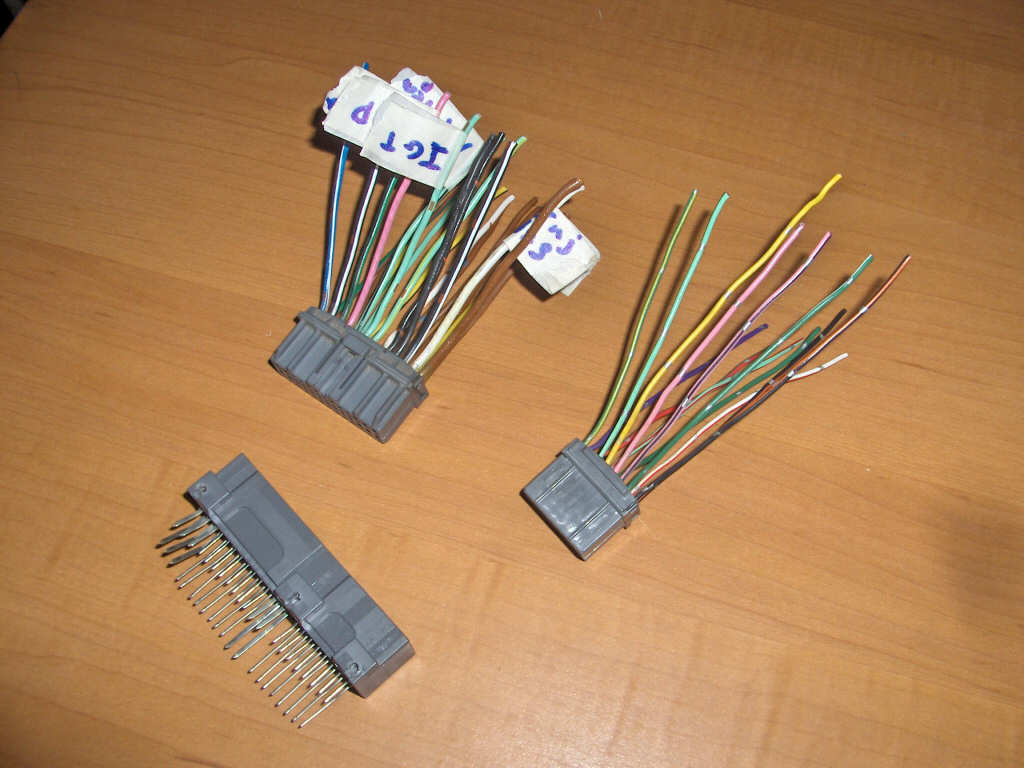
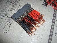
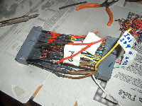
Now that that is done we move on to the other half of our harness. Take the connectors that plug into the harness and label the wires you will need for your controller. In this case I am hooking up the E-manage. So, I have labeled fuel injector wires along with ignition, manifold absolute pressure, ignition power, ground, speed, throttle position, coolant temperature, and air intake temperature. Find what wires your going to need and label them. To do this just get a hold of the pinout diagram for your ECU. In my case I was using a manual ECU from a 1992 Tercel. For different years the wiring may be different. It also helps to go through the E-manage harness and label all the wires that will need to be attached too. That way you don't forget anything. I found one on mine that I had missed previously.

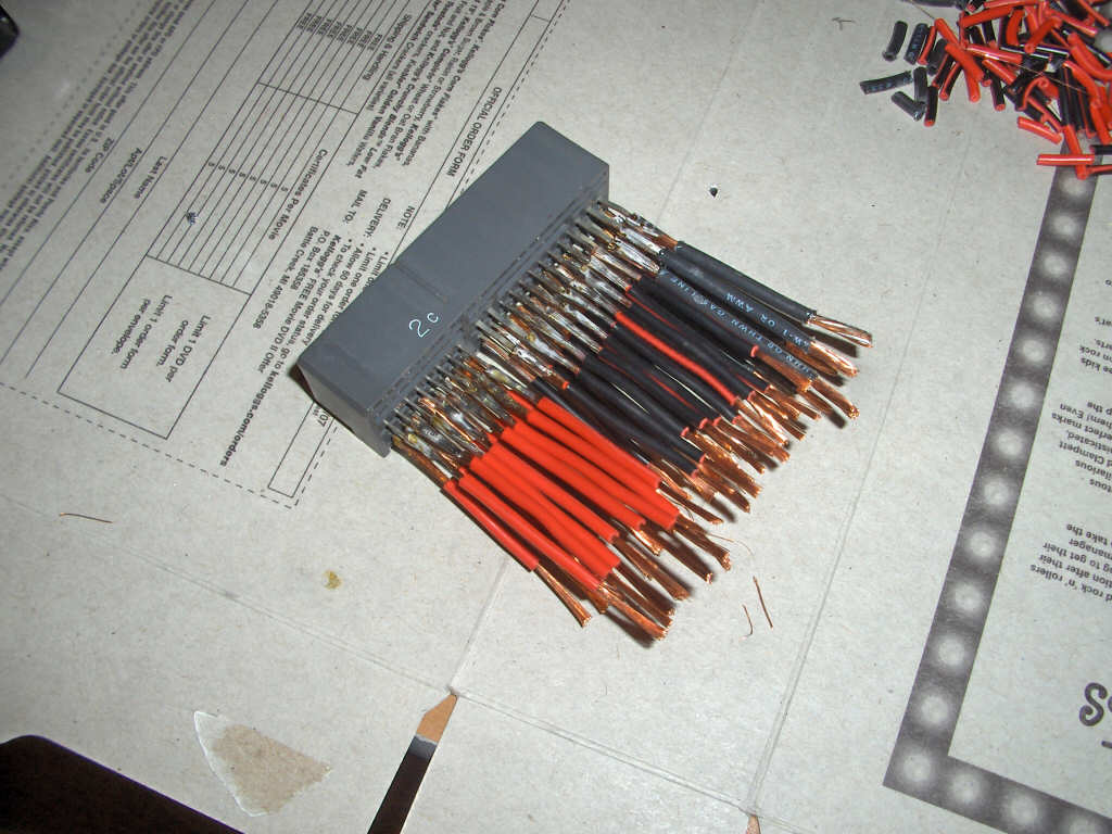
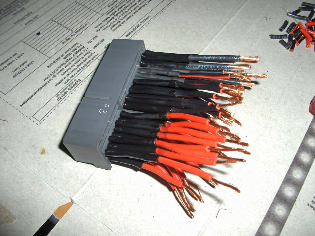
Now that you have everything labeled we can work on the other side of the harness again. Take the connector you disconnected from the board and start soldering wires to it. You may not need to hook up all the wires but it never hurts. You can use any size wire for this as long as it is the same or larger gauge than the wire they will connect to. In my case I had some 14 gauge wire in my garage and used it for everything. Theres no need to make the wires real long. Just make them long enough to work with. I would also highly suggest using heat shrinking wrap on all these wires. Lets do it the right way.


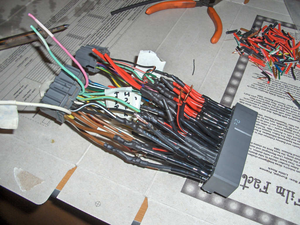
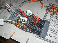
Now that you have that half soldered up go ahead and start connecting the corresponding wires to the other side of the harness. A word of warning, there are a few wires here. Take your time and double check your work. Make sure you skip wires if they're missing from the colored harness side. I just put some shrink wrap over the ends of the wires on the other side so they don't touch anything. Its easy to loose track so watch this carefully. Also, be careful to watch for your labeled wires and make the right connections to them. If you are just splicing into the signal solder the two wires together and add a third for the spliced lead. If you are splitting the signal make sure you don't solder those wires at all. Once you are done with the soldering crimp any connectors on that you need. Now kick back and breath that solder resin smoke filled air and admire your handy work. Your done!
BACK