BACK
Making a Turbo Manifold
Written by: Daox
So, you finally bought that CT-9 you've been waiting for. Now its time to bolt it on and have fun! Or, maybe you've gotten used to what used to be the amazing power of the stock 4E-FTE and just want a little bit more out of the 'ol CT-9. But, first you need a new turbo manifold, right? You vaguely remember something about the 4E-FTE's manifold and its bad #3 cylinder runner. Read on and see whats needed to remedy that.
My task here was to make a replica of a 4E-FTE turbo manifold that will be fitted to a distributorless 5E-FE. As it is written, this is a general guide of what I went through to make the manifold. It is by no means the only or the best way to make one. Deviate from the DIY wherever you feel necessary.
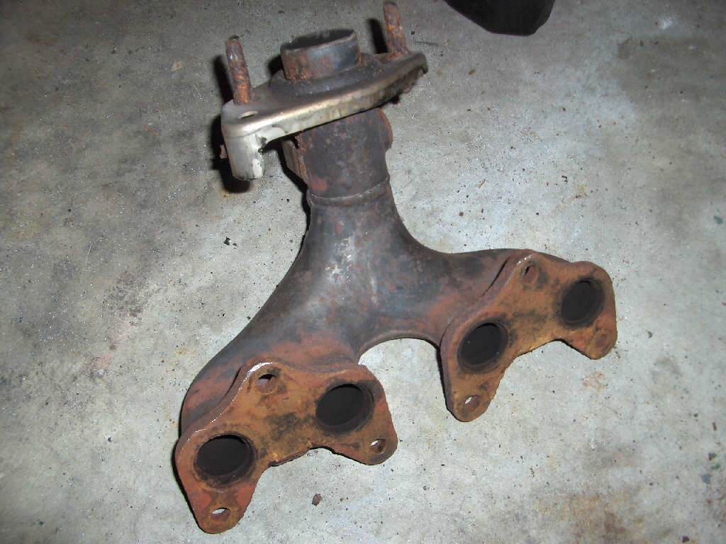
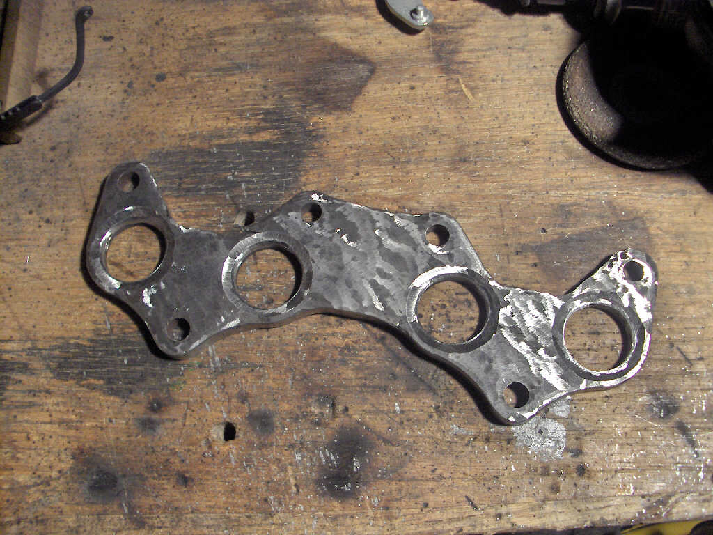
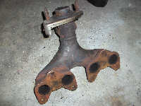
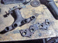
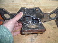
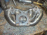
I started with the stock 5E-FE DIS manifold. I wanted to use it so I didn't have to remake the head flange. However, the problem with this manifold is that there are two seperate flanges.
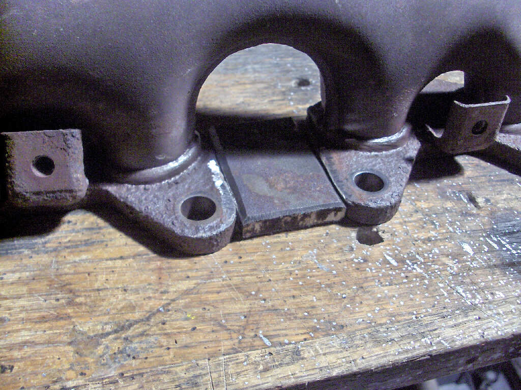
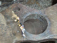
So, to make one solid flange (which makes fabbing the manifold 100x easier) I cut up some steel to bridge that gap.
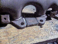
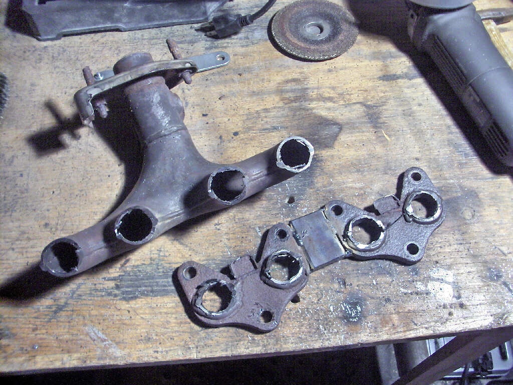
I tacked it in place, and welded the back side. I then cut off the rest of the manifold.
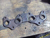
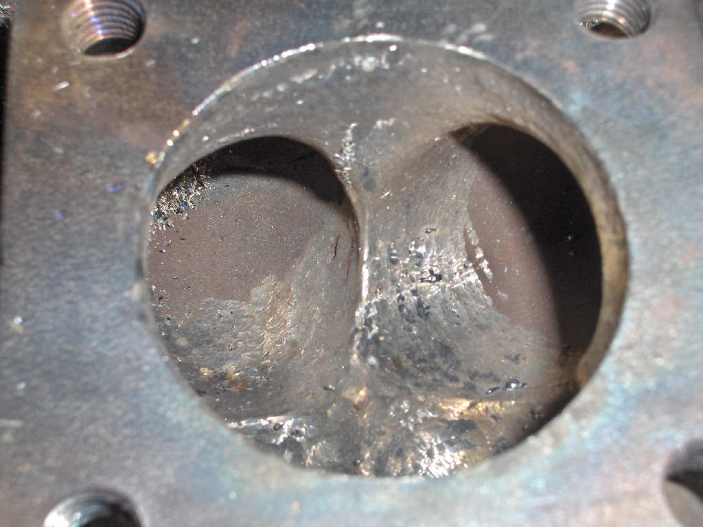
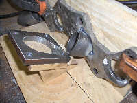
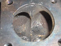
After cutting the rest of the manifold off I ground the flange flat. Note: I didn't grind on the mounting side of the flange. That surface must be kept perfectly flat to seal properly.
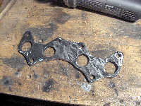
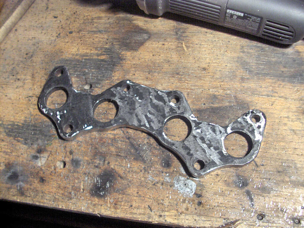
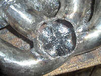
Now, to get a little room and a better and stronger weld joint I chamfered all the edges of the runner holes very heavily. Presto-chango we have a flange ready to be welded up to be a turbo manifold.

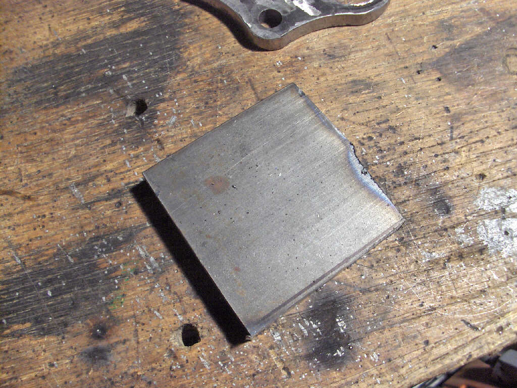
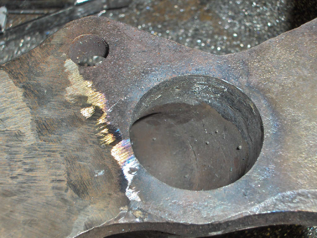
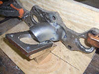
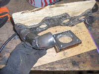
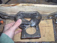
Of course, we still need a turbo flange for the other end. So, I grabbed a sheet of steel and cut it to size.
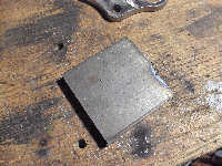
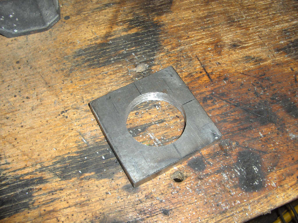
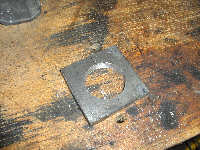
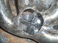
This next step was the one I was wondering how I was going to pull off. I needed to punch a 1-7/8" hole in that 3/8" thick square piece of steel. I tried a few things and then ended up picking up a Milwaukee hole saw and arbor. Amazingly the saw worked great. It took a while (and a bit of oil) to get all the way through the plate but it did work nicely.
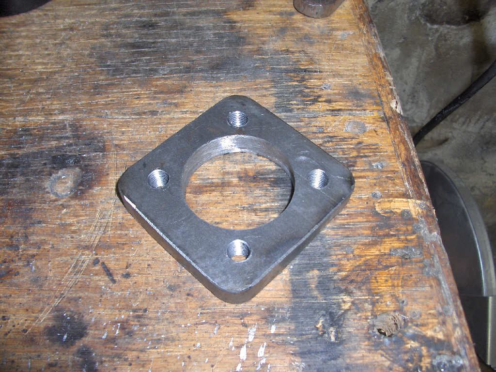
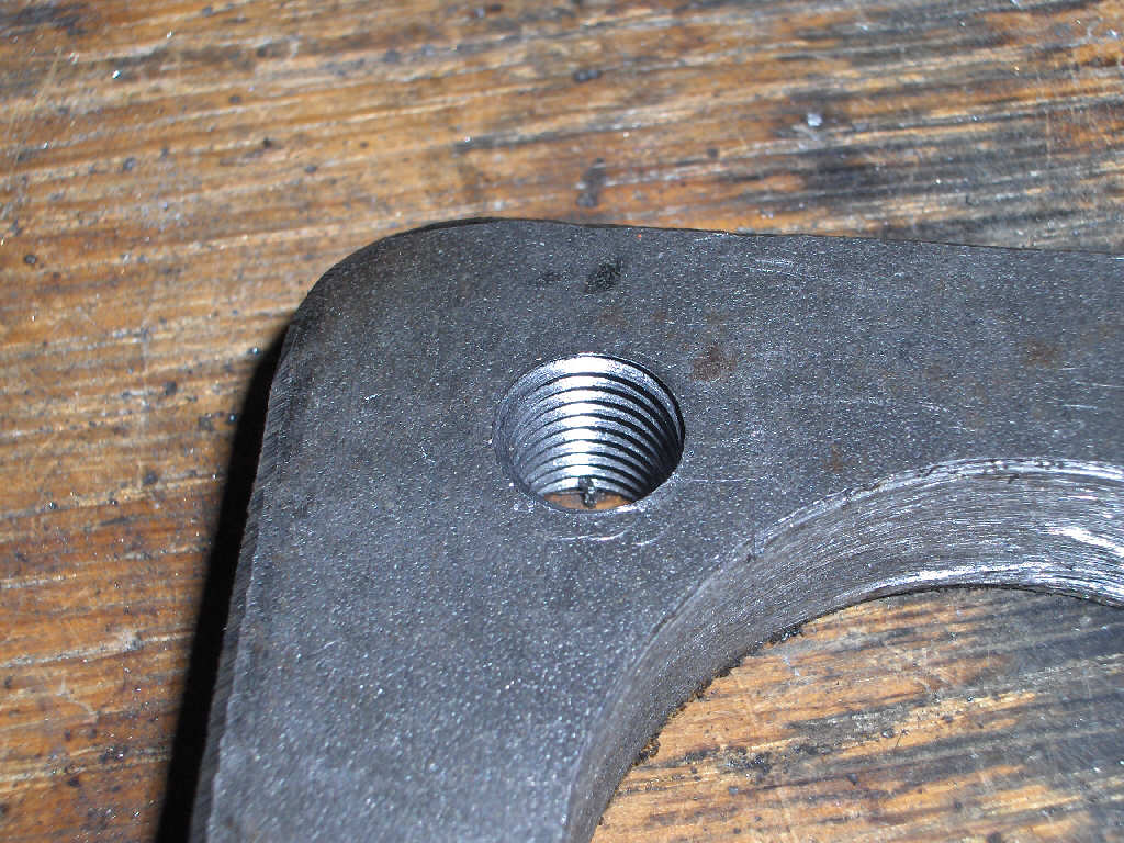
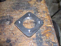
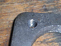
Next up is to put the stud holes in each corner so the turbo can bolt up to it. Easy enough. Drill and tap the four M10x1.25 holes. Also put a radius on the corners to smooth it out. There we go, its a turbo flange. Nice clean cut threads too.
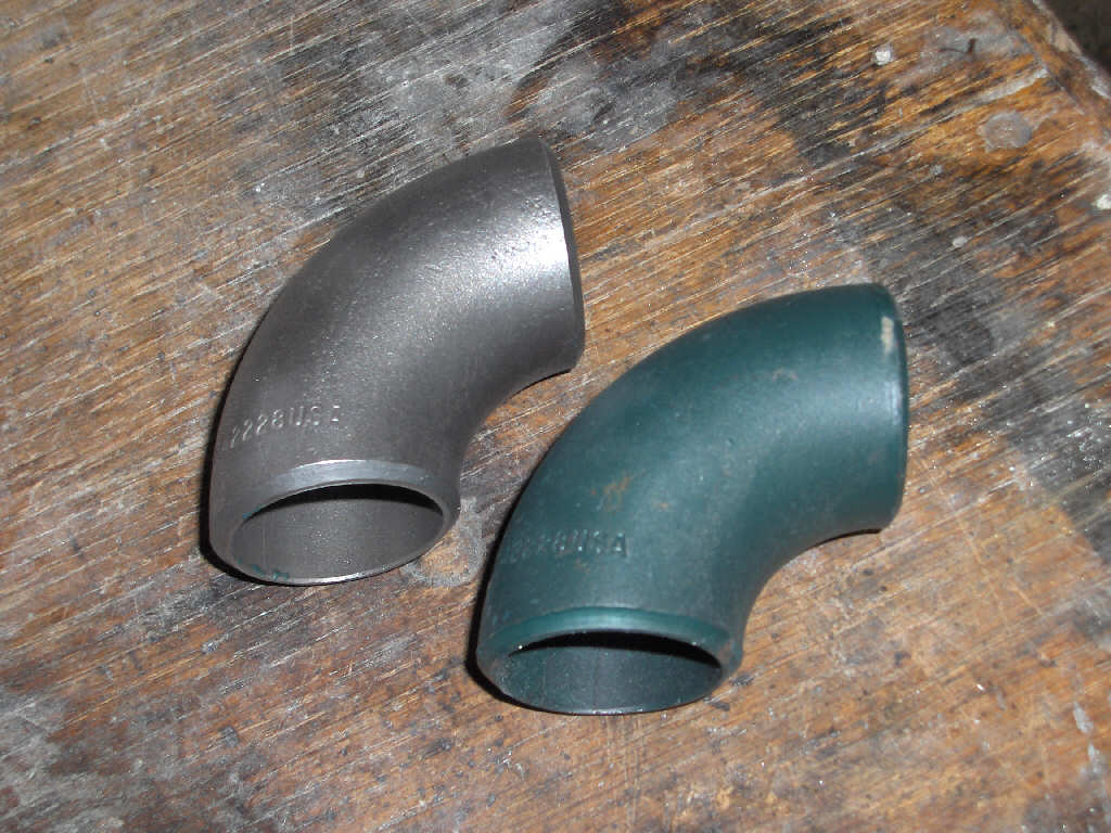
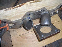
So, now we have both ends. The next step is connect them. We start off with mild steel butt weld fittings much like the ones in the box below.
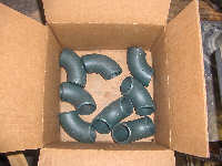
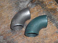
However, you really need to clean off the green coating as it will contaminate the welds. My preference for removal here is definitly the sandblaster. However, a rough sandpaper would do along with a ton of time because that stuff isn't soft. After your done they should look nice and shiny! Remember to get the inside and outside, especially if your going to paint or coat the manifold.
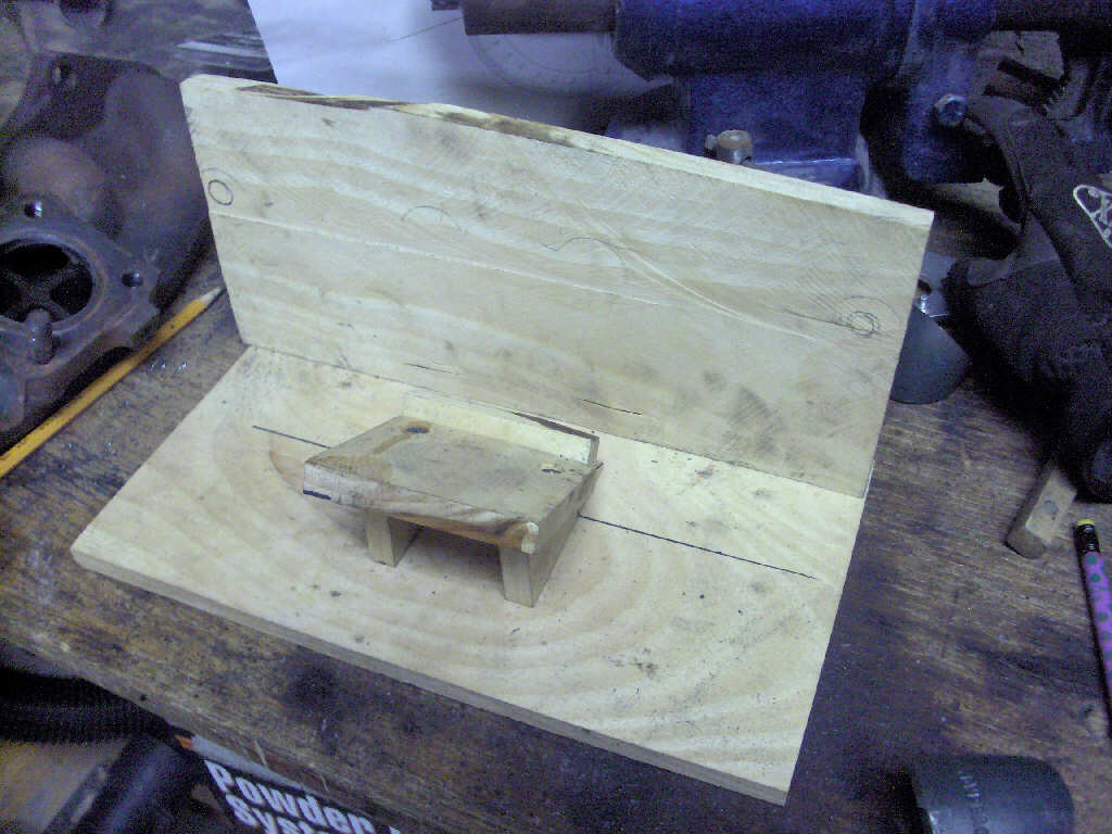
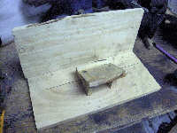
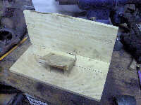
Continuing on with the connecting part, I decided a simple fixture was the best way to go since I am trying to replicate the CT-9 stock manifold. So, I came up with what you see below. It is very simple, but it does the job very well.
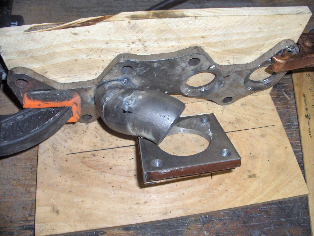
So, from here on out we just have to fit and cut and weld the runners. First, we fit. I start with the inner runners as the outter ones will be made around them due to space restraints. Use a black marker to indicate where the tubes match up to each other and the flange so it is easy to get them into place after grinding. FYI you'll be doing a ton of grinding so I hope you have a nice angle grinder. Test fit, grind, test fit, grind... will be your mantra.
With hind sight being 20/20, I really should have chamfered all my edges before tacking everything together, but I didn't. I highly recommend this as it took me a lot of time to take it all apart, rechamfer, and then reweld it. So, ignore that my tacks aren't chamfered and go ahead and do it right away on your manifold. Also, make sure your chamfers on the pieces are big enough so the weld penetrates the joint as far as possible.
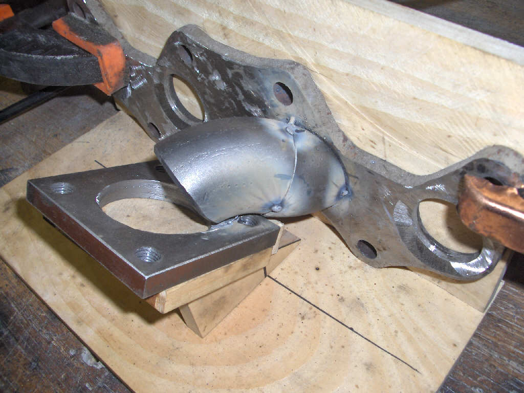
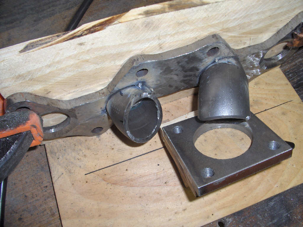
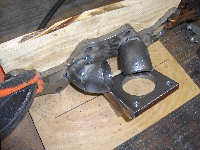
Tack weld the sections together for test fitting. I started with the #3 runner. As you move along the runner make sure to take a die grinder and deburr the insides of the runners for better exhaust flow.
Runner #3 is looking good, now for #2. Again, working from the inside out so I know I have room to go around if I need to.
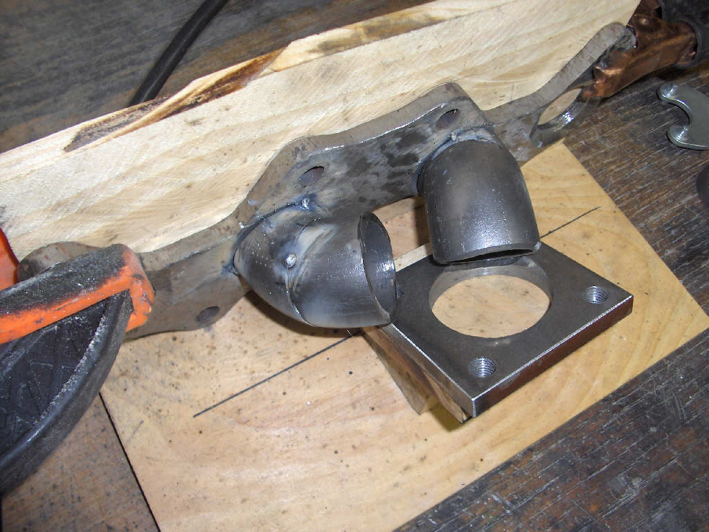
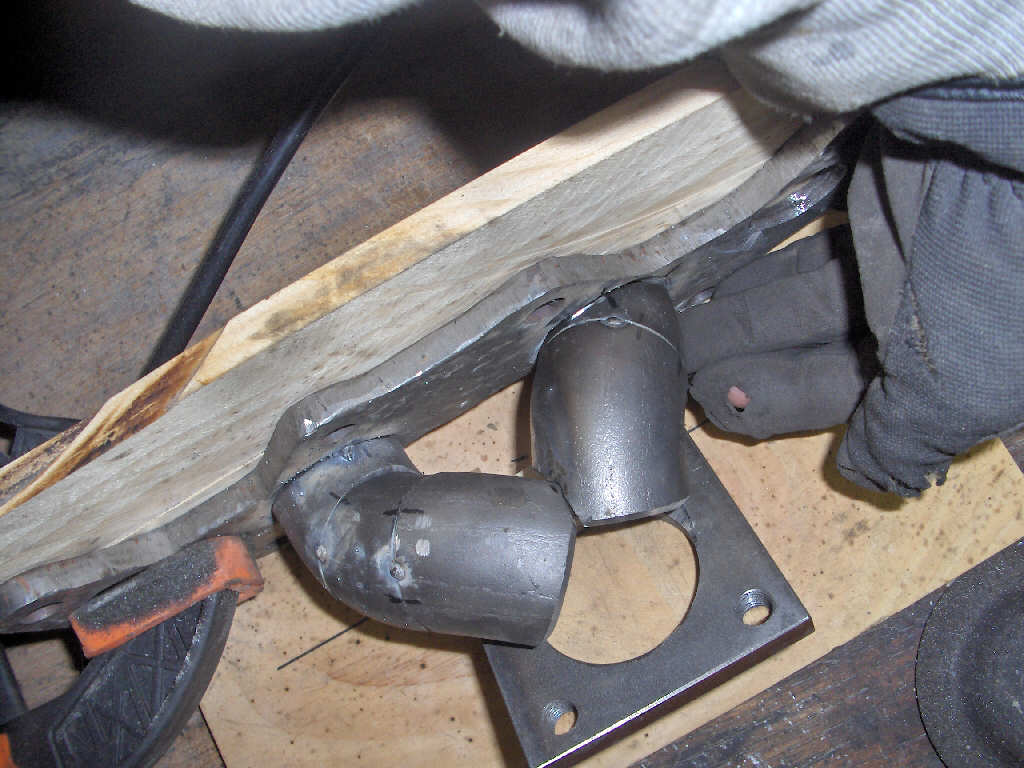
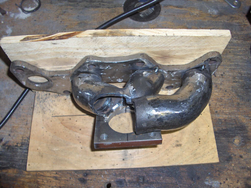
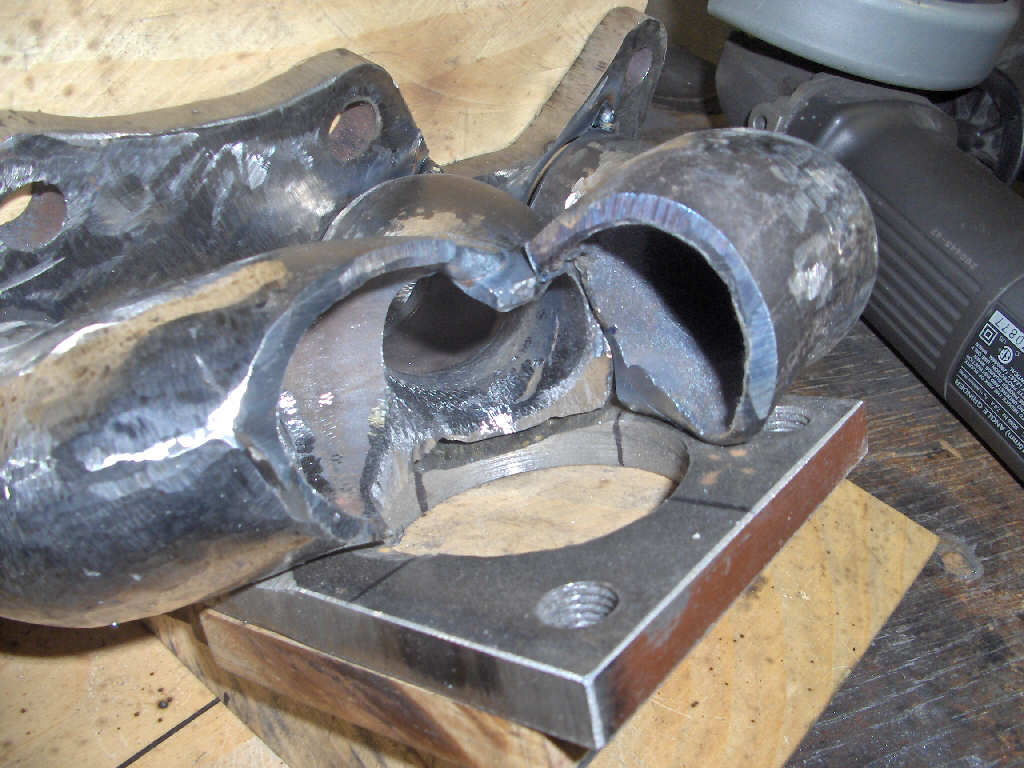
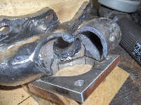
Now, the two runners have to come together. Start cutting... carefully, and come up with something like this.
Next comes runner #4.
And, last but not least, runner #1.
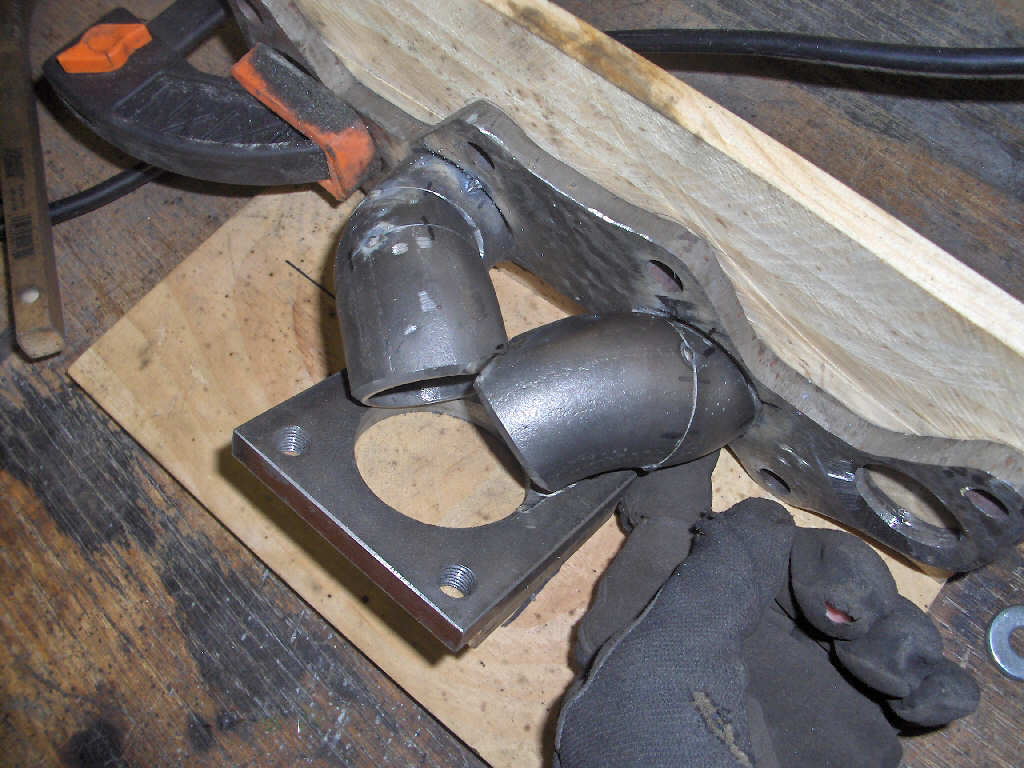
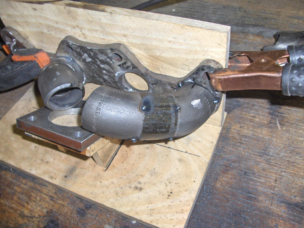
Now that all the runners are made and fitted to each other it is time to finish weld them together. I welded the #2 and #3 runners together... In hind sight don't think this was the best way to go. I'm think it would be easier to do #1 and #2 together, then do #3 and #4, then put those together due to the angles these pieces come together at. Of course I think of this after I've already done the welding... If you want you can go ahead and grind the outside of the runners as well. As you can see, I did.
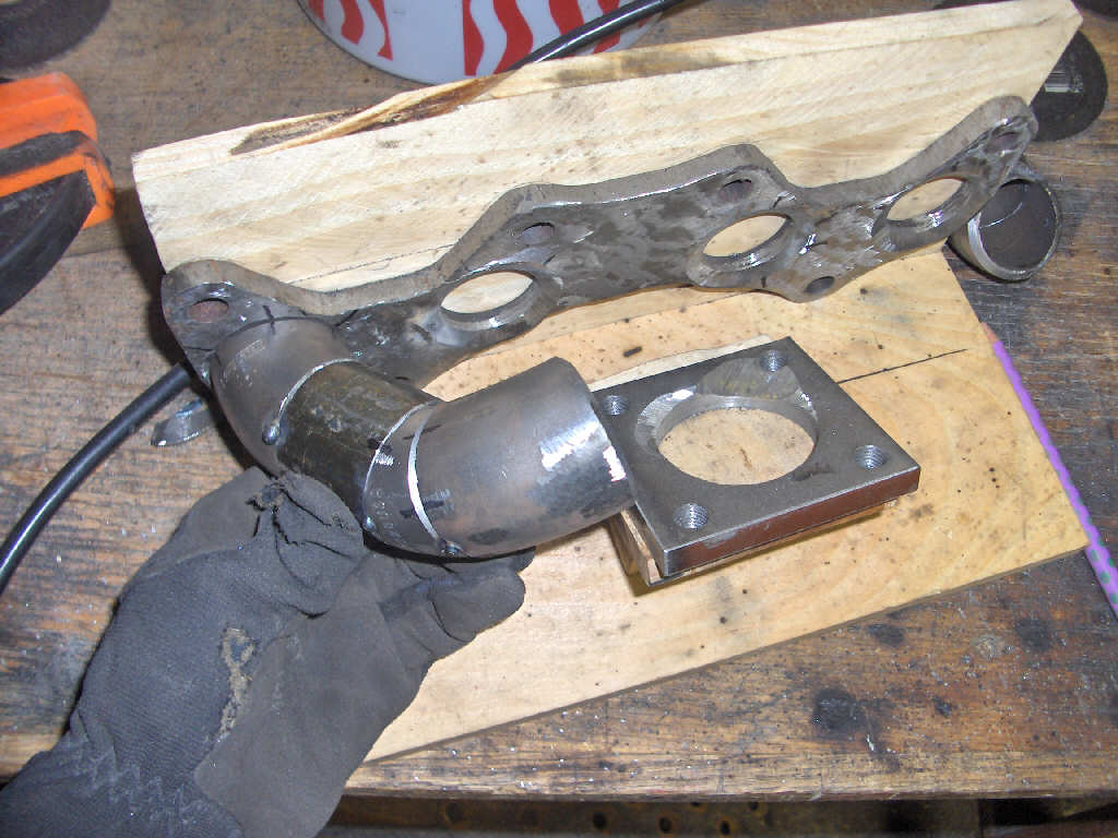
Next is forming the #4 runner up to the #3 runner. Lots of grinding to get these to fit nice.
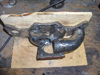
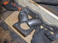
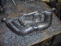
Here is the whole thing together with #1 just tacked on to see how it fits up.
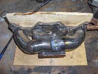
Now we weld the last runner on completely. Forgive the less than steller welds. I'm good, but definitly not the best.
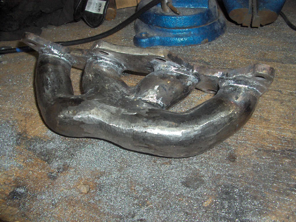
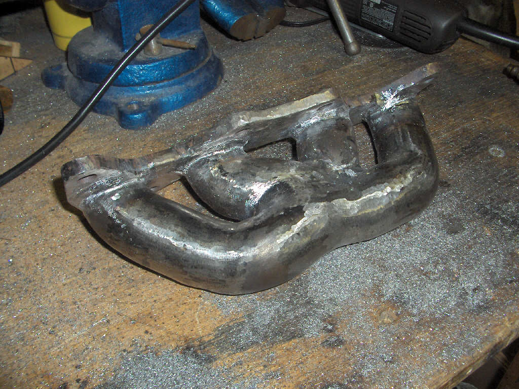
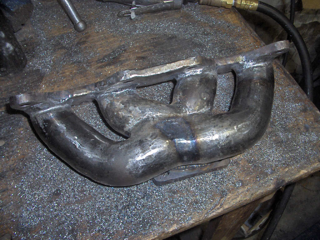
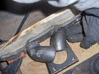
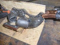
Finally, with it all welded up its time to grind more! Of course, the amount of grinding is totally up to you.
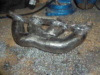

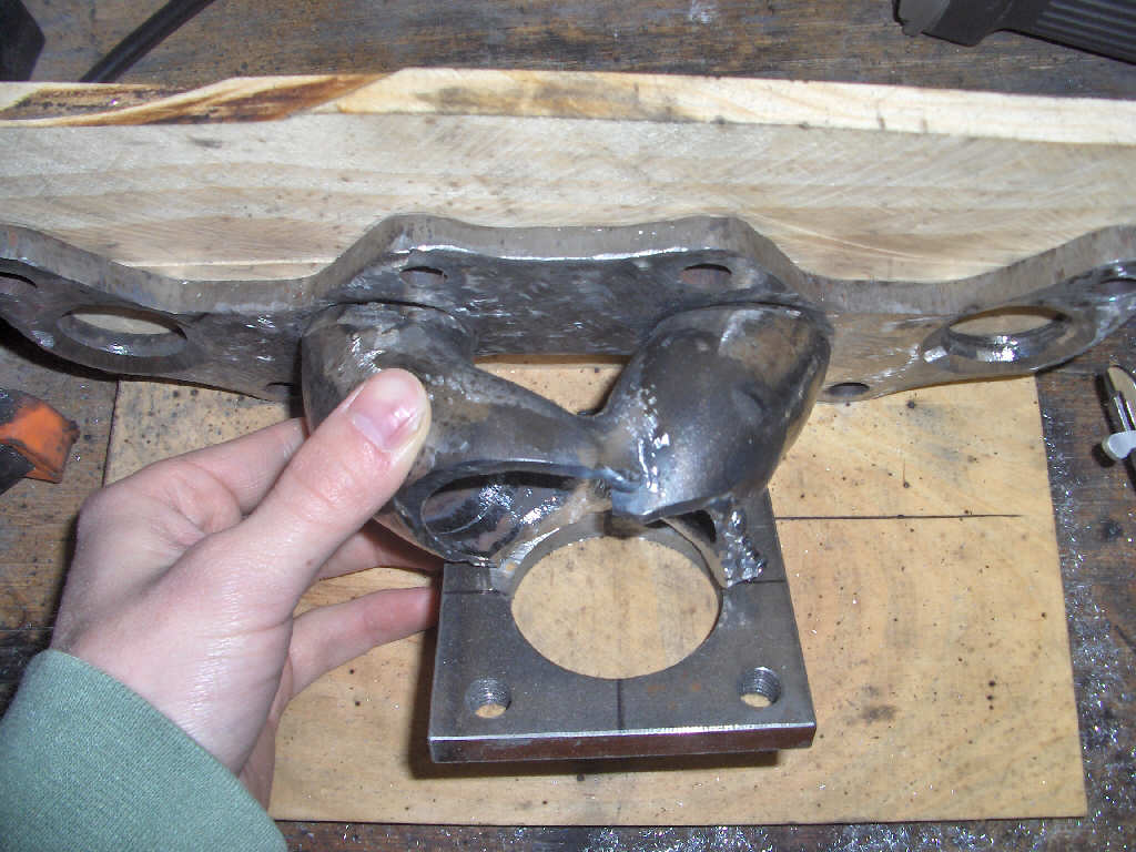
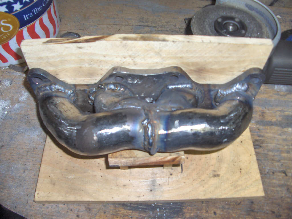
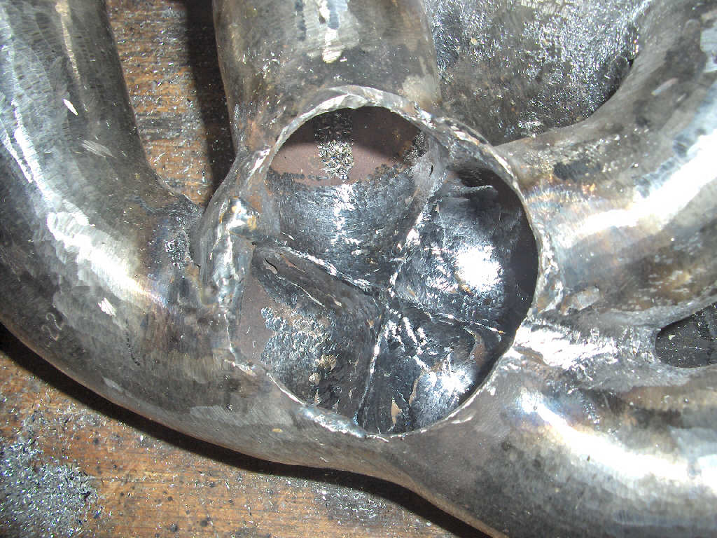
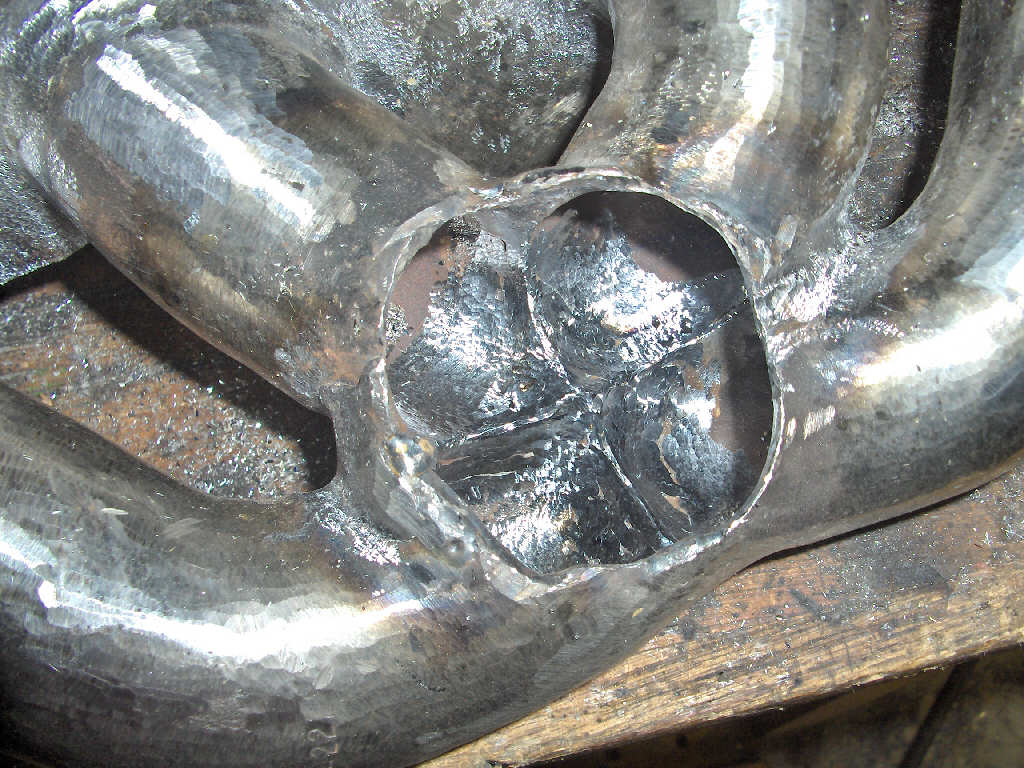
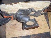
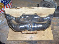
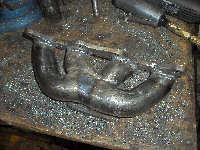
After the outside is all ground its time to take a look at the collector area. Weld and grind back your welds to create a smooth flowing collector.
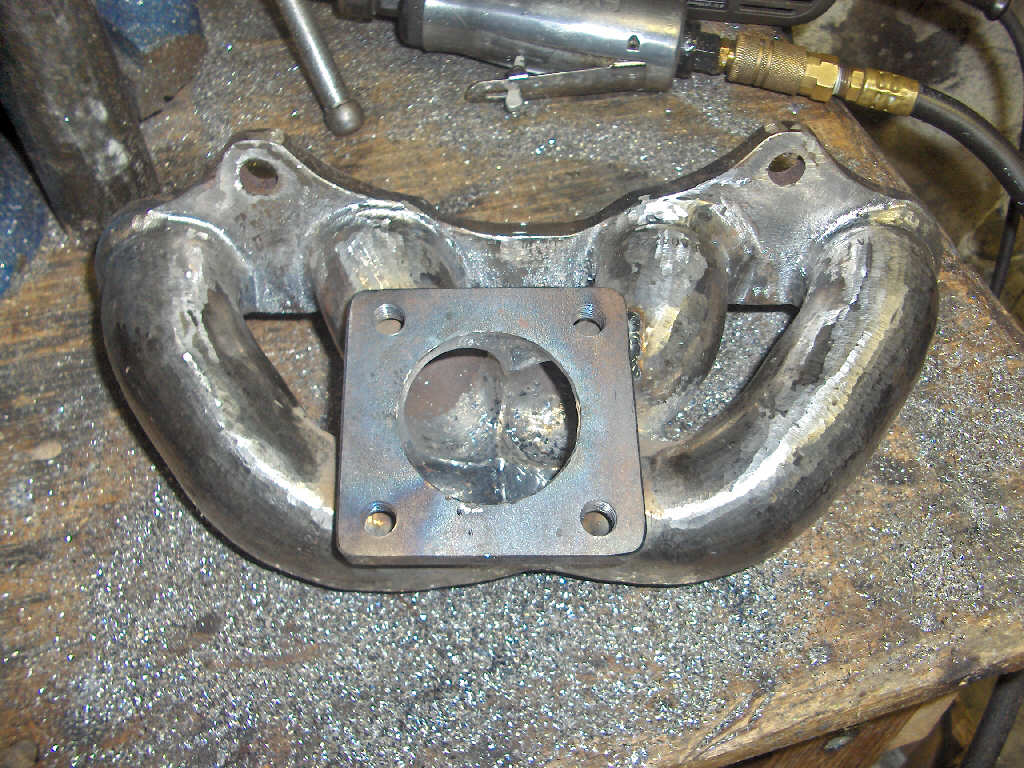
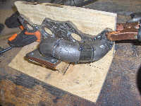
Finally, put the whole thing back on the fixture and fit up the turbo flange and tack it on. Finish weld when you are happy with the fit. Make sure to grind back the welds for good flow.
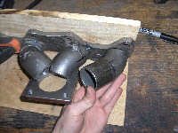
Almost done! The final step is to weld the inside of the runners and the joint with the head flange. Again grind the welds back down to ensure proper exhaust flow.
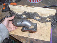
There we have it, a nice new turbo manifold for your car. You'll probably want to at least spray on some high temperature paint after all this hard work, or send it out for ceramic coating.
If it seems simple just reading about it here, its really not. This is an incredible hour consuming project that isn't for the faint of heart. There is a reason these items cost so much if you have to go out and buy them. However, if you have the time and tools and the willingness to try something new, go for it!
BACK