After some thought I figured it would be wise to create a page with information on the development of the intake manifold insulators. At the time of development this site was just starting out and I didn't think to put it up. I have now gone back and collected all the research data and it is presented here. I tried to recreate my standard format of always having the newest news at the top.
6/29/05
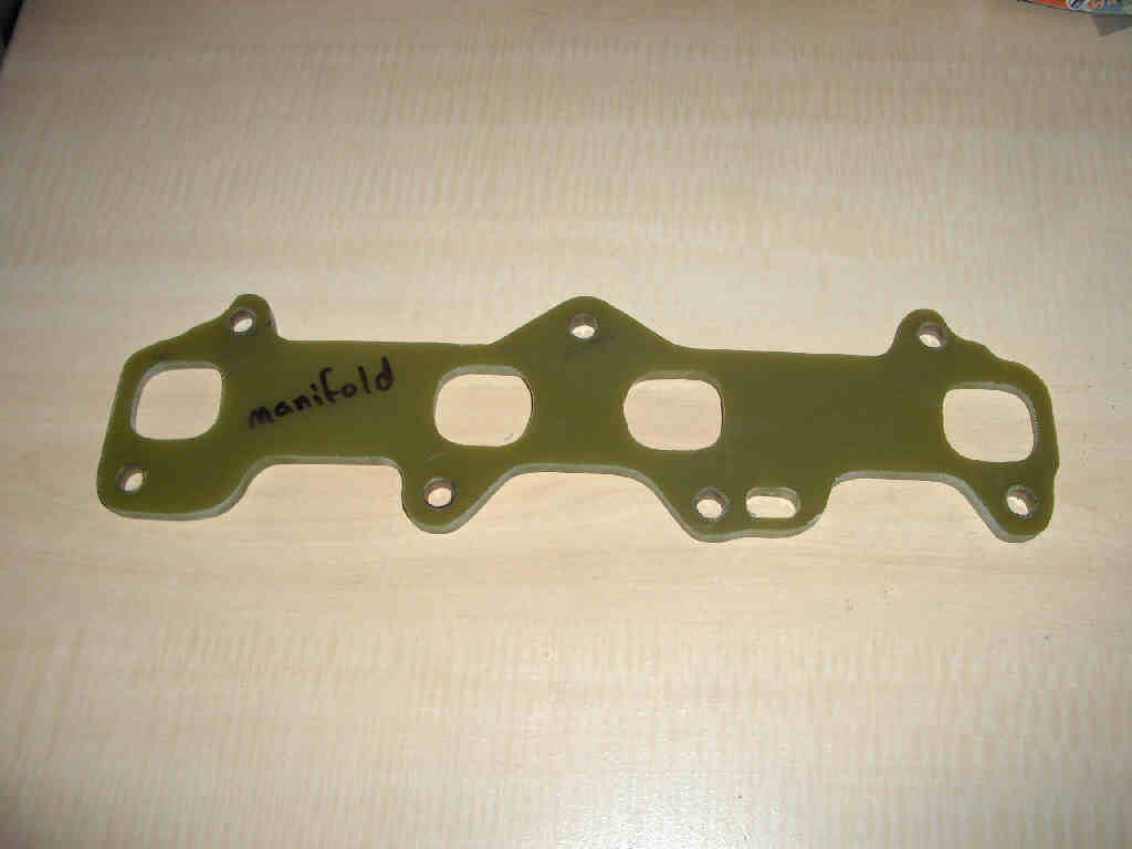
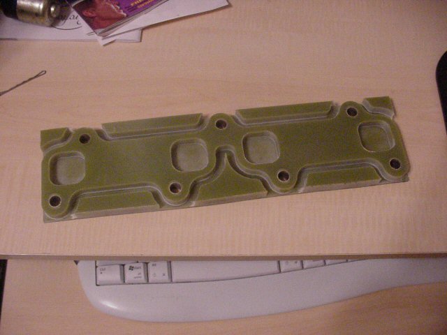
Just to tie everything up here's the 3E-E (left) and 1st gen 5E-FE (right) final designs:
6/24/05
The testing is completed now and I am just waiting to get my tested insulator back to make the necessary changes. The conclusion was (at least on the 3E-E) that the insulator will hold up to the exhaust gas heat. However, if you have an EGR system on your 3E-E (and 1st gen 5E-FE) it is not going to give you the same gains. The manifolds for these items have hot exhaust gas running through them. The insulator will hold up to the hot exhaust but the heat transfered by that exhaust is not avoidable. This means the insulator would definitly block some heat but its not going to be as efficient as a car without EGR. There is also the fact that engine coolant flows through the intake manifolds on these engines. I still have to gather some information but I can probably block the coolant from entering the manifold. This will eliminate a huge source of heat. The EGR needs to be there. If you block it you'll throw the check engine light.
However, there is a solution to this as well, but it involves more work and might not be worth it to you. If you really want to use this mod you could use the insulator to block the exhaust gas from flowing through the intake manifold and disconnect the EGR valve. Normally this would throw the check engine light. However, if you have an ECU from a car without an EGR system you should have no problems as the ECU won't be looking for the EGR to effect the system. Again this is not tested but just a theory that I've come up with.
So what does this all mean Daox? Quit blabering on an on. Ok, lets do a quick recap. This means the 3E-E, 1st gen 5E-FE, 4E-FTE, and 5E-FHE insulators are ready to go! Cars with EGR systems will not see the gains as cars without EGR systems. There is a fix but its not tested and its obviously more expensive.
4/20/05
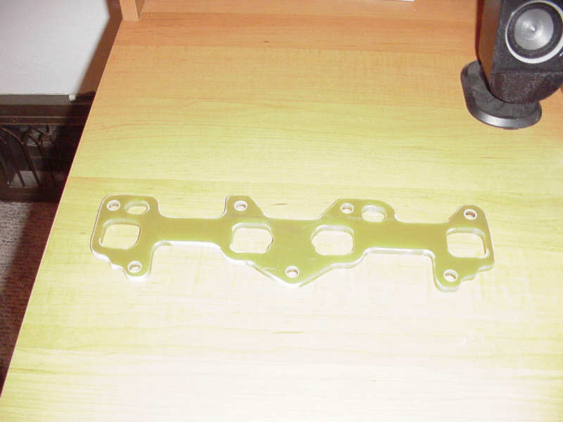
Well, I finally had some free time on my hands so... here you go 3E-E people:
I appologize for the bad picture... the camera was freaking out. I got this shot, and one other worse one, and then it just died.
4/18/05
I just realized that the insulator I had made won't work on a 3E-E with an EGR (exhaust gas recirculation) system. So I have to go back and tweak a few things.
It's the same for the 1st gen 5E-FE, 4E-FTE, and 5E-FHE. I think I am going to need a test subject again. My tester did a great job but his car does not have an EGR system. I have some worries about the high temperature of the exhaust and the insulator since the exhaust gas travels through the intake manifold intead of in a seperate tube, as is the case on the 2nd gen 5Es. I can't imagine this being insanely hot, but at the same time it is the air that just came out of a cylinder that had an explosion in it... I do think it will be ok as the insulator material can withstand quite high temperatures. I want to make sure before I sell something that won't melt into your engine. Until this is tested I can't really recommend putting these on 1st gen 5E's with EGR systems. The same will go with the 3E-E until I can get someone to test that because my 3E-E doesn't have an EGR system either and the 3E-E uses the intake manifold to route the exhaust gas back into the intake. Other than that, you can feel free to order an insulator from me for your 1st 5E-FE, 5E-FHE, or 4E-FTE.
4/10/05
The 1st gen 5E-FE insulator has now been tested. It fit and worked properly. The tester definitly noticed cooler intake manifold temperatures.
3/30/05
So, here we have it folks. The 1st gen 5E-FE insulator. Still working out a definite person to test it though.
3/27/05
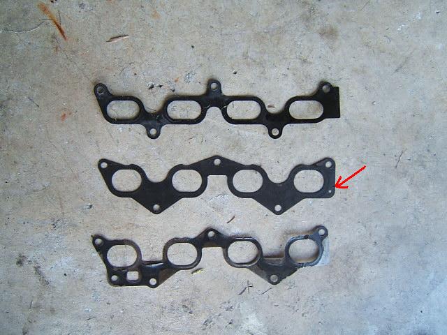
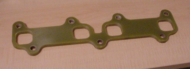
Something I noticed and am looking into... on the the foreign 4E-FE and 2nd gen 5E-FE engines there is a small hole in the gasket. I'm guessing its some port for vacuum by the size of it. If it is necessary, the insulator will have to be redesigned to include it. This really isn't a problem for the 1st gen 5efe and 4eftes, but only the overseas engines. Its really not a huge deal. I can design the insulator with the hole, it just means moving everything over a little bit (I did it already and it looks fine). But, if I don't have to I don't really want to.
See the middle gasket to see what I'm talking about:
3/23/05
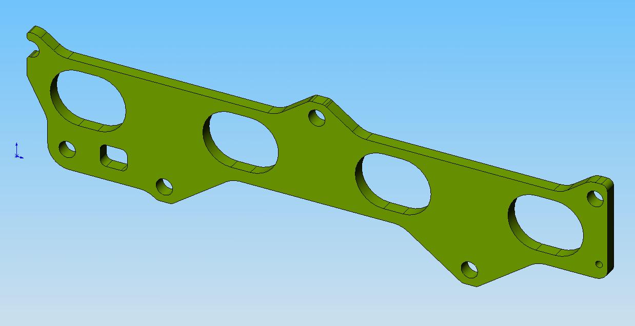
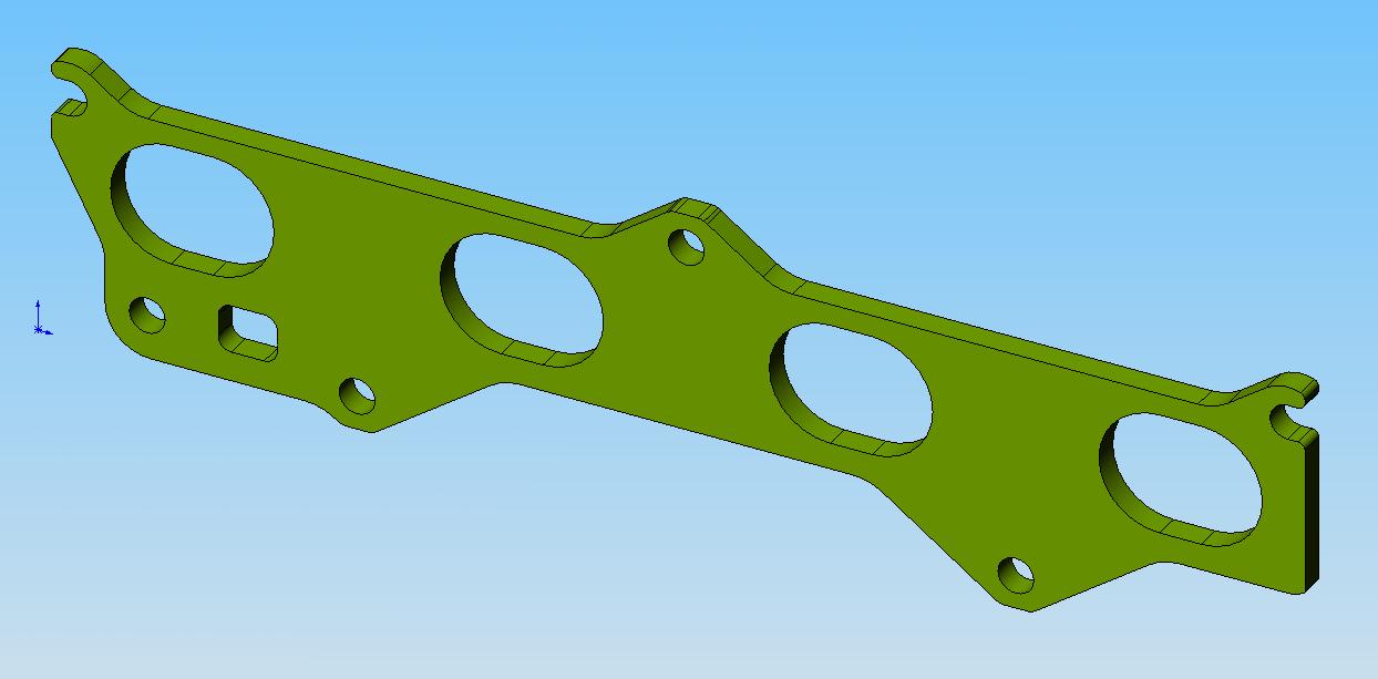
After doing some work and buying some parts I bring you the preliminary design on the 1st gen 5E-FE insulators. These will also fit your 4E-FTEs and 5E-FHEs as well as the 2nd gen distributored 5Es. I'll be meeting up with a 1st gen 5E-FE owner this weekend to work out the details, but I don't anticipate much changing between now and then. If that is the case I'll need someone to test fit the insulator and let me know if there are any problems, because I don't have an engine to test fit it on.
3/11/05
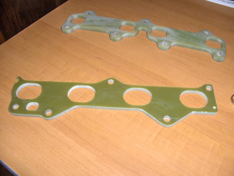
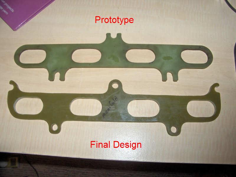
Well, its a bit of work to make, but here is a shot with both the prototype and the new design that will be for sale. The new design is only cut off on the far bolts. Thats the edge of the material. Sorry fellas, it doesn't get any better then that. I did install and test it and it seals great so I will be making more shortly. Here are pics of the prototype (top), and the final design (bottom).
3/3/05
Well I just got out of the garage. The 'ol 96 blackhawk is purrin like a kitten with the insulator in place.
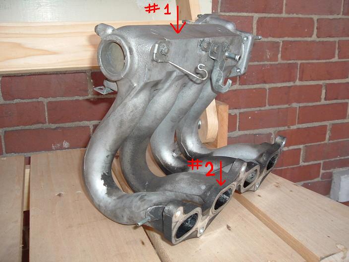
Time for testing! I just took a casual drive around to see how the insulator holds up and got some temp readings. I must say, they look good. Here we go:
Stock:
ambient: 28�F
Point #1: 80�F
Point #2: 147�F
Insulator Installed:
ambient: 27.5�F
point #1(top): 75�F
point #2: 95�F
Thats a 52 degree drop! Looks like in order to drop that 75� at point #2 much more, we'll need a throttle body insulator. But I'm not surprised by that.
I also went and made my 12 runs at the same exact location as before for consistancy's sake. Here are the results (technical mumbo jumbo below because I know you just want the numbers):
Stock: 76.8 hp
Insulator Installed: 80.1 hp
Horsepower Increase: 3.3 hp
A few things to note here. One, I am very happy with this increase. Two, it was 27� at the time I left, it is now 25� as I just got home. This can be attributed to a little bit of that increase as it was slightly warmer (28�) on the first/stock test. Three, I encountered a brake problem tonight and my brakes were scraping. The pad on the drivers side front is worn down and scraping the rotor, thus creating drag. Obviously drag is bad, and wouldn't be there normally. This effects the gtech readings and would tend to decrease the horsepower reading, although I don't think it effected it much (less than .5 hp). Those are the variables (except for me being happy) so take them as you will. Oops, sorry, one more note. This insulator is the gift that keeps on giving. Since it provides a % hp increase (in this case 3.3/77.8 = 4.2% increase) it is the mod that keeps on giving. Only an estimate, but running a 200hp 4EFTE with this mod would give you roughly a 8.5 hp increase just from the cooling factor, thats not including if you advance timing. The calculations say 5 degree drop in air temp = 1% horsepower increase. With that said, this mod is probably dropping your air temps about 20 degrees. I don't know how much that can help with advancing timing, but I'm sure it won't hurt. Another upside is that this increases your torque throughout the entire powerband. No decreases anywhere so your not giving up anything.
Now, onto the other good stuff I'm sure you all want to know. Daox, when/where can I get my handy dandy intake insulator? Well that is something I have been thinking about. I, personally, can not make these on a mill all day long. On a side note my company was recently bought out. Now is not a good time to start doing projects under the new owner's nose. Future insulators will not be CNC made unfortunately. If it consoles you at all though, the insulator used for testing was modified to a fair degree by myself and does match up very near perfectly to the head and manifold. I am looking into how I can completely make these at home. Very soon I will be ordering more material to make a second round of these. This will also expand my line up to the 3E-E and 1st gen 5E/4E/5EFHE engines.
2/24/05
Well, I got the insulator installed, but the rest of the intake is not fully back together. I will say it is a pain to get the prototype on the head. There are 3 studs on the top and 2 holes on the bottom. With my bolt holes actually being slots there was no way to hang the part on the head while reinstalling the manifold so I had to fidget for a while to get it on... not fun. Needless to say, all further intake insulators will not have this problem. There is also another concern of mine. I currently have the insulator fairly thick. This only allows the nuts to screw on about 1.5-2 threads. I did push and pull on the manifold and it is solid, but I don't really like this idea. So I may end up making it thinner, but I will do some on-road testing to see how it holds up. It will probably be fine with the other brackets on it. The bolts did seem to go in further than the nuts, and that should help. I have considered using longer studs, but I am not wanting to make that a necessity for installation. I'm aiming this as more of a bolt on type of modification.
Heres a teaser pic. You can see it lines up very well with the manifold. The ports also match up beautifully.
2/21/05
So, I finally went out and did some testing with the gtech. I found a good section of road and did 13 runs. As of now, being stock, the average of all those runs is 76.8 horsepower. Remember this is measured with a gtech, it doesn't measure horsepower at the crank or at the wheels. It measures actual horsepower after every possible power loss is factored in (air friction, friction of your tires on the road, wheel bearing friction, everything). This seems very close to what the car should be putting out. The engine makes 94 peak horsepower at the crank. The standard deduction for a manual transmission is about a 15% reduction. That brings me down to 79.9 horsepower. Add on those other things (friction deductions) and 76.8 horsepower seems about right.
2/11/05
Alright, time for initial testing results. Unfortunately, I didn't get to use my new gtech pro competition. The competition model requires RPM calibration to calculate horsepower correctly. I do not have a tachometer on that car so it won't be possible to use the competition. I will make runs with my regular gtech pro, however I did not today as it was snowing and I want solid readings. At this point everything is stock except for a K&N panel filter. Stock intake, stock everything.
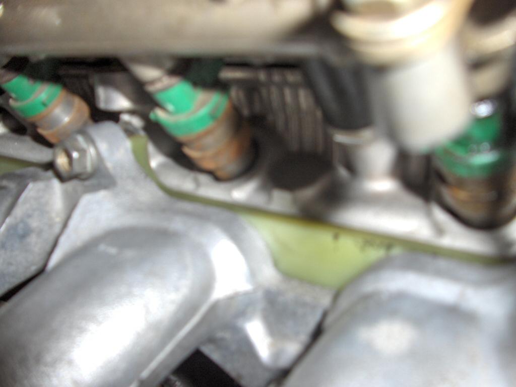
So our temperature reading today were made with a surface thermometer and gave these readings:
Ambient temperature (temp outside): 28�F
Point #1: 80�F
Point #2: 147�F
Refer to the previous photo to see where points 1 & 2 are. These measurements are an average of a few measurements taken. All the measurements were very close. Also, they were taken after the car was warmed up, and after about 15 minutes of casual city driving. I didn't go make a power run then stop and check them quickly. These should be very realistic numbers. As you can see, down near the head that sucker is pretty hot.
When the weather clears up I will be making some runs with the gtech to get some horsepower numbers. I did do one run today but I don't think its accurate and I wouldn't just post 1 run. You need a handful, and then average them out to get a real number.
1/24/05
I'm rounding the final bend on my 2nd gen 5E-FE rebuild. Tonight the rest of the intake will go back on and testing will commence. I will probably go a week without the insulator on the car and make sure everything is working fine. I will take surface temperature measurements off the intake manifold at two spots. The first spot will be off the top of the intake plenum. The second will be taken off of a runner/flange itself that is right up against the head. I will also be doing runs with the Gtech, and measuring temps between runs. Unfortunately, I can't get temp measurements of the air itself right in the intake manifold's runners as this would be the best way of measuring the gains of the insulator.
12/16/05
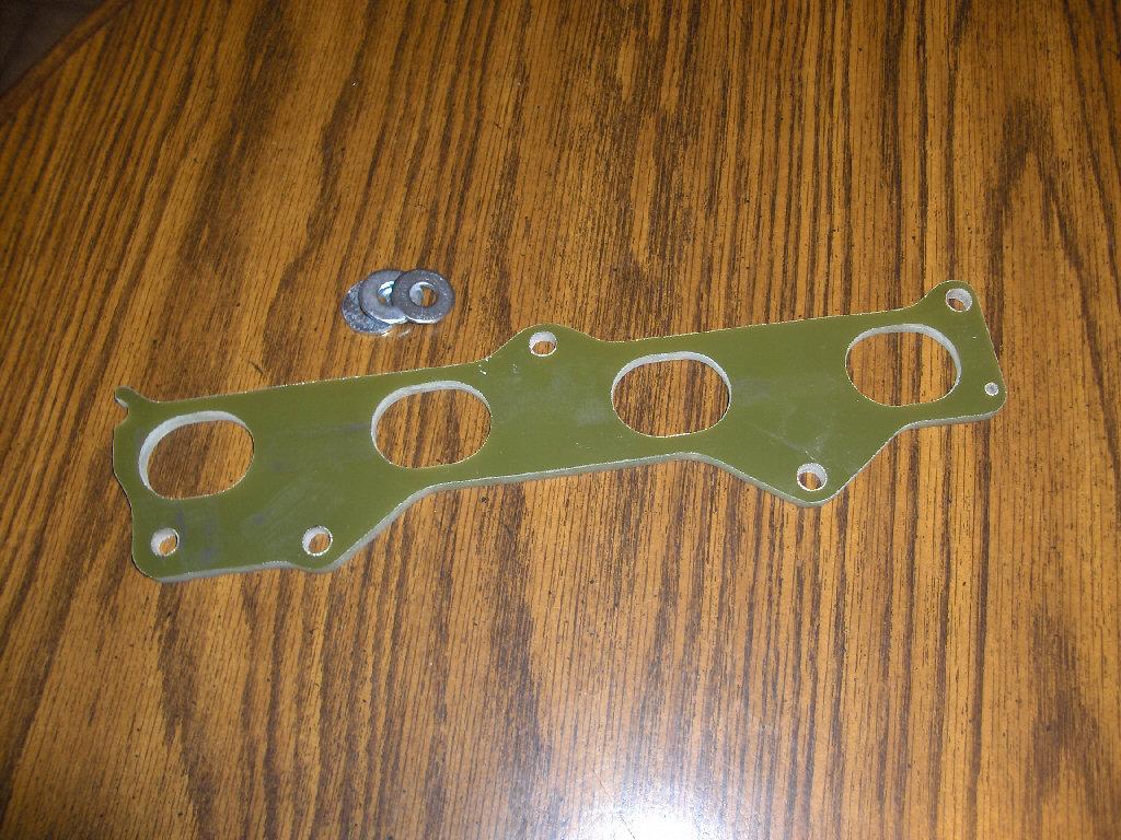
The 5E-FE insulator is done! Check out the pictures below.
11/1/05
Here is the 3ee finished insulator. This won't be going into the car until I am done with the 5efe rebuild I am working on right now. So, the 5efe will have the not-yet-made insulator installed before this.
10/31/05
I have drawn up the first design for the 2nd gen 5E-FE insulators. I had to slot the bolt holes because of lack of material size. Again, the material size wasnt quite long enough to get the last 2 bolts on each end. In any case it shouldn't matter, they still hold on to the manifold itself and that will sandwich the insulator more then adequately.
I also just got done doing the majority of the machinging on the 3ee insulator. I must say it is comming out very nicely! The next step will be milling off the back side to the width I have chosen. That will clean it up and it'll be ready to install after a bit of deburring.
10/25/05
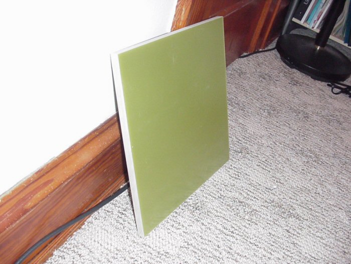
Well, the material finally arrived after almost a week of UPS not finding my house. This stuff is pretty dang hard. Depending on the finish I get after I am done machining it, you may need RTV sealant to keep it airtight. There's always the possibility of surface grinding it but I'd rather not go into that...
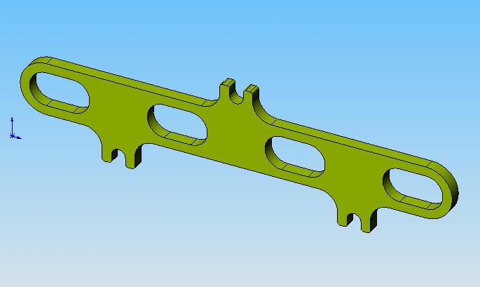
Current plans are to bring it to where I work and get it machined. There it will go on a CNC mill. The first insulator to be made will be for the 3E-E engine. I just happen to have an extra intake manifold laying around that I could make the template off of. This is the initial design for it.
10/18/05
The material has been ordered for the prototypes. This is the beginning of my first project, which is intake manifold insulators. These insulators go between the head and theintake manifold. The purpose is to block the transfer of heat from the head into the manifold, and thus keep the intake air cooler. This will keep the air denser and give you more power.
These are some images I collected off of another site explaining how the insulators work.